Anatomy of a Node: Difference between revisions
No edit summary |
No edit summary |
||
| (3 intermediate revisions by the same user not shown) | |||
| Line 1: | Line 1: | ||
__TOC__ | |||
The logic nodes system is a visual approach to building and scripting logic within the ARCADIA editor. It has many similarities to typical written scripting language, such as variables, lists, conditionals, etc. | The logic nodes system is a visual approach to building and scripting logic within the ARCADIA editor. It has many similarities to typical written scripting language, such as variables, lists, conditionals, etc. | ||
| Line 28: | Line 28: | ||
<p>These nodules are the data used by the nodes to configure their behavior. Similarly to execution nodules, there are Input Data Nodules, which are the parameters controlling the node’s behavior, and Output Data Nodules, which are the results from the node behavior.</p> | <p>These nodules are the data used by the nodes to configure their behavior. Similarly to execution nodules, there are Input Data Nodules, which are the parameters controlling the node’s behavior, and Output Data Nodules, which are the results from the node behavior.</p> | ||
<p>Data is sent together with execution, but it’s the execution nodules which control whether a node will accomplish its behavior.</p> | <p>Data is sent together with execution, but it’s the execution nodules which control whether a node will accomplish its behavior.</p></br> | ||
{{CustomHeader|Title=Connecting Nodes}} | |||
Nodes are connected by arrows, indicating the direction of the execution. The tail of the arrow indicates the sender, while the point indicates the receiver. | |||
Only nodules of identical signatures can be connected together : Execution nodule to execution nodule, actor nodules to actor nodule, etc. | |||
There are two ways of connecting nodes: | |||
<h3>Nodule to Nodule Connection</h3> | |||
Using the left mouse button, drag from the sending nodules to the receiving nodule. | |||
<div style="border: 1px solid #473ba7; border-radius: 8px; background-color: #050522; padding: 10px; box-shadow: 0 2px 5px rgba(0,0,0,0.1); margin: 10px 0; float: left; width: 450px; margin-right: 35px; "> | |||
[[File:LinkingNodes.jpg|center|link=|450px|450px]] | |||
</div><br><br><br><br><br><br><br><br><br> | |||
<h3>Multiple Selection Connection - 2D linking</h3> | |||
Selecting your sending node first, then selecting the receiver node while holding control, will allow to connect nodules using the logic linking UI. Check [[2D Logic Linking]] page for more details on how this works. | |||
<div style="border: 1px solid #473ba7; border-radius: 8px; background-color: #050522; padding: 10px; box-shadow: 0 2px 5px rgba(0,0,0,0.1); margin: 10px 0; float: left; width: 450px; margin-right: 35px; "> | |||
[[File:2DLinking.jpg|center|link=|450px|450px]] | |||
</div> | |||
Latest revision as of 09:41, 24 June 2024
The logic nodes system is a visual approach to building and scripting logic within the ARCADIA editor. It has many similarities to typical written scripting language, such as variables, lists, conditionals, etc.
Nodes range from simple building blocks like math operators to full systems like complete UI panels or complex queries allowing to morph the player into any object, or to spawn a vehicle.
This allows to quickly build fully featured experiences, while still retaining the flexibility to customize and design your own features.
Components of a Node
A node is typically split into three types of nodules:
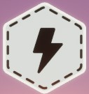
Header
Icon at the top of the node. It indicates at a glance what node this is, and allows you to select and move the node.
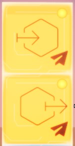
Execution Nodules
These nodules are responsible for controlling the execution of the nodes. Typically, all nodes will have some Input Execution Nodules, which will trigger the node behavior, and Output Execution Nodules, which will be fired when the node has executed its behavior.
You can distinguish Execution Nodules by their Orange colour, which is unique to this type of nodule.
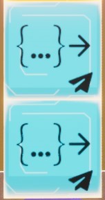
Data Nodules
These nodules are the data used by the nodes to configure their behavior. Similarly to execution nodules, there are Input Data Nodules, which are the parameters controlling the node’s behavior, and Output Data Nodules, which are the results from the node behavior.
Data is sent together with execution, but it’s the execution nodules which control whether a node will accomplish its behavior.
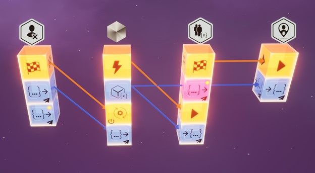
Connecting Nodes
Nodes are connected by arrows, indicating the direction of the execution. The tail of the arrow indicates the sender, while the point indicates the receiver. Only nodules of identical signatures can be connected together : Execution nodule to execution nodule, actor nodules to actor nodule, etc.
There are two ways of connecting nodes:
Nodule to Nodule Connection
Using the left mouse button, drag from the sending nodules to the receiving nodule.
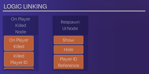
Multiple Selection Connection - 2D linking
Selecting your sending node first, then selecting the receiver node while holding control, will allow to connect nodules using the logic linking UI. Check 2D Logic Linking page for more details on how this works.